Introduction
The purpose of this class was to built a robotic, autonomous car that could navigate its surroundings. This required us to contend with various sensors, non-linearities, feedback control, and embedded programming. The goal of this lab was to implement navigation through a room with our car. We started with building the robot's hardware: sensors, motors, and wiring. Then, we implemented the software: PID loops to control orientation and linear position, a Kalman Filter to merge sensor data, and Bayes filtering to localize the robot in a room. Finally, it's time to put all of this together and let the robot navigate itself through the room.
Key Parts
The system in composed of three main parts:
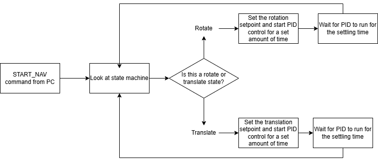
State machine to step through the different phases of the robot's movement, angular PID control to rotate the robot to a setpoint, and linear PID control to move the robot precise distances.
For the PID control, I wrote a small library to reduce the spaghetti code that I wrote in previous labs. This consisted of a PID class that would be initialized with control parameters, and a method to compute the control signal. The class also has a method to reset the internal state of the PID controller.
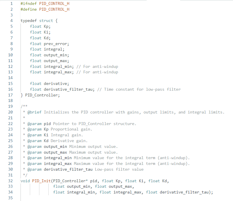
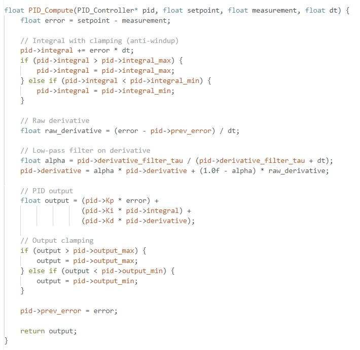
Here's the core method of the PID class. It takes the setpoint, sensor, and time as inputs, and returns the control signal. I included clamping on the integral term to prevent windup, and I also included a lowpass filter on the derivative term to reduce noise. The low pass filter is implemented as a simple first order filter, and the cutoff frequency is adjustable based on the initalization of the PID class.
Challenges
The biggest challenge I faced in this lab was hardware and spaghettification. I spent some time in the beginning of the semester to build a high quality robot, and everything held up very well up until this lab. For some reason, but motor controllers became unresponsive for a while, which took up valuable debugging and development time.
The other challenge I faced in this lab was spaghetti code. Up until this point, everything I wrote was in one big file, and much of my code approached 1500 lines. This made the code difficult to read and maintain, especially because there were sections that were repeated. One of the things I did to reduce the spaghetti code was to write a PID class that would handle the PID control for me. This is because PID control is used in two places in this program, but the execution is the exact same. It just has different parameters, which makes it a perfect fit for object-oriented programming.
Writing the PID class was a good first step, but I still had a lot of code that was repeated due to the state machine. This ended up making my file over 1000 lines long, but it was still more readable because the code was organized into blocks that were easy to follow. I think the next step for me is to write a state machine class that would handle the state machine logic, to offboard the state machine logic from the Artemis to my PC. This would also increase flexibility, as the robot would not need to be reflashed to change the state machine.
One other challenge I faced was compile time. Compilation took multiple minutes for me each time, which slowed down my development process. I think this is because of the global libraries including ArduinoBLE, ICM20948, and SparkFun_VL53L1X. I tried creating a separate c file that would import the libraries in a way that would cache the compiled code so that they don't have to get recompiled each time, but I couldn't get it to work. The Artemis compiler is apparently known to be heavy, and I think in future robotics projects, I will try to use a different microcontroller that has a faster compiler.
System Logic Diagram
Development
Since this lab involved a lot of "putting it all together", I wanted to make sure that the elements that I was putting together already worked well in isolation. I started with the angular PID controller, and tested it with setpoints from the original Lab 6, as well as Lab 9.
Then, I moved on to the linear PID controller, and tested it with setpoints from Lab 5. In both controllers, I switched to using the PID class that I wrote, and I was able to get the robot to rotate and move in a straight line even better than before. I think this is because the PID class is more robust than the code I wrote in previous labs, and it also has more finely tuned parameters. Increasing the lowpass filter on the derivative term helped a lot with noise, and I think the integral term is more stable now too because I added the dt term to the sum.
The only thing I'd do differently in hindsight is to offload the state machine logic to my PC. I think this would have made the code a lot cleaner, and it would have also made it easier to change the state machine without having to reflash the robot. Especially because the compilation time is so long, I think it would have been worth it to do this.
Execution
Here's a video of the robot navigating the room with the PID controls and state machine:
Results and Discussion
The core decision I made in this lab was to use a state machine to control the robot's navigation through the space. The alternative would have been to use the Bayesian filter to localize the robot, and then give it delta_angle_1, delta_distance, and delta_angle_2 setpoints to allow it to navigate through the space. If my robot had not broken, I think I would have been able to do this, but I think the state machine is a good alternative considering the circumstances.
If I were to implement the Bayesian filter, I would have created three commands: CHANGE_ANGLE, LINEAR_MOVE, and SAMPLE_DISTANCE. The CHANGE_ANGLE command would take in a set delta_angle, and move the robot accordingly. It would do this by sampling the DMP yaw angle at the beginning of command call, adding the setpoint delta to that, and then using the PID controller to rotate the robot to that angle. The LINEAR_MOVE command would working in a similar fashion, by measuring the current distance to the wall, and then setting the setpoint to that distance plus the delta_distance. Finally, SAMPLE_DISTANCE would just take a few samples of the ToF sensors, and return that single value to the PC.
The alternative to this architecture would be to have a MOVE command that takes care of delta_angle_1, delta_distance, and delta_angle_2 all at once, and a GET_OBSERVATION command that works similar to Lab 9's mapping command, and return that data for the localization. This would be a marginally easier to implement on the PC side, but it would make the Artemis code more complicated and more spaghetti-like because of the multiple control states. Especially since flashing the Artemis takes a long time, I would want to make the embedded-side code as simple as possible. Also, writing a simple method to replace loc.get_observation_data() and traj.execute_time_step() would not be too difficult.
Conclusion
Overall, I'm quite happy with how this lab turned out. I think it a fair job integrating all of the different parts of earlier labs in this class, and I learned a lot about the importance of modularity and code organization, especially in integration projects like this. I think the biggest takeaway for me is that I need to work better around system weaknesses, such as the long compilation time. Putting the state machine on the microcontroller was not a wise idea, and I had enough information when starting this lab to know that I should have put it on the PC. Regardless, I think the robot turned out well, and I'm happy with how it performed.