The two DC motors that control the left and right sides of the car are controlled by PWM, so
I needed to make sure that the pins that go to the motor controllers are all PWM-capable. The
PWM capable pins on the Apollo3 microcontroller are the pins with the tilde (~) sign. I used
pins 9, 11, 12, and 13. Two of these pins went to each motor controller, as well as a ground
line for each.
Separate Batteries
Batteries have output impedance that can cause drops in voltage when a lot of current is
demanded from them. Since we are driving motors, there will be a large load on the battery
hooked up to them, and if the whole system is powered by one battery, then the microcontroller
and sensors will all see voltage line fluctuations caused by the motor. In addition, the motor's
physical commutator, inductance, and backEMF sends a lot of noise back up the power line, and
this would also negatively affect everything else, so using separate batteries ensures all the
messy signals are isolated to one part of the circuit, and the sensors and sensitive electronics
are powered by a different, cleaner voltage line.
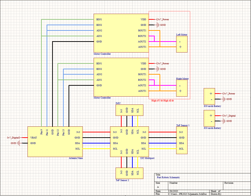
Intended Diagram
Here's a diagram of my car's system, including motors, motor controllers, Artemis (with pinout),
and batteries. You can get the schematic as a pdf here.
Lab 4
Benchtop Testing
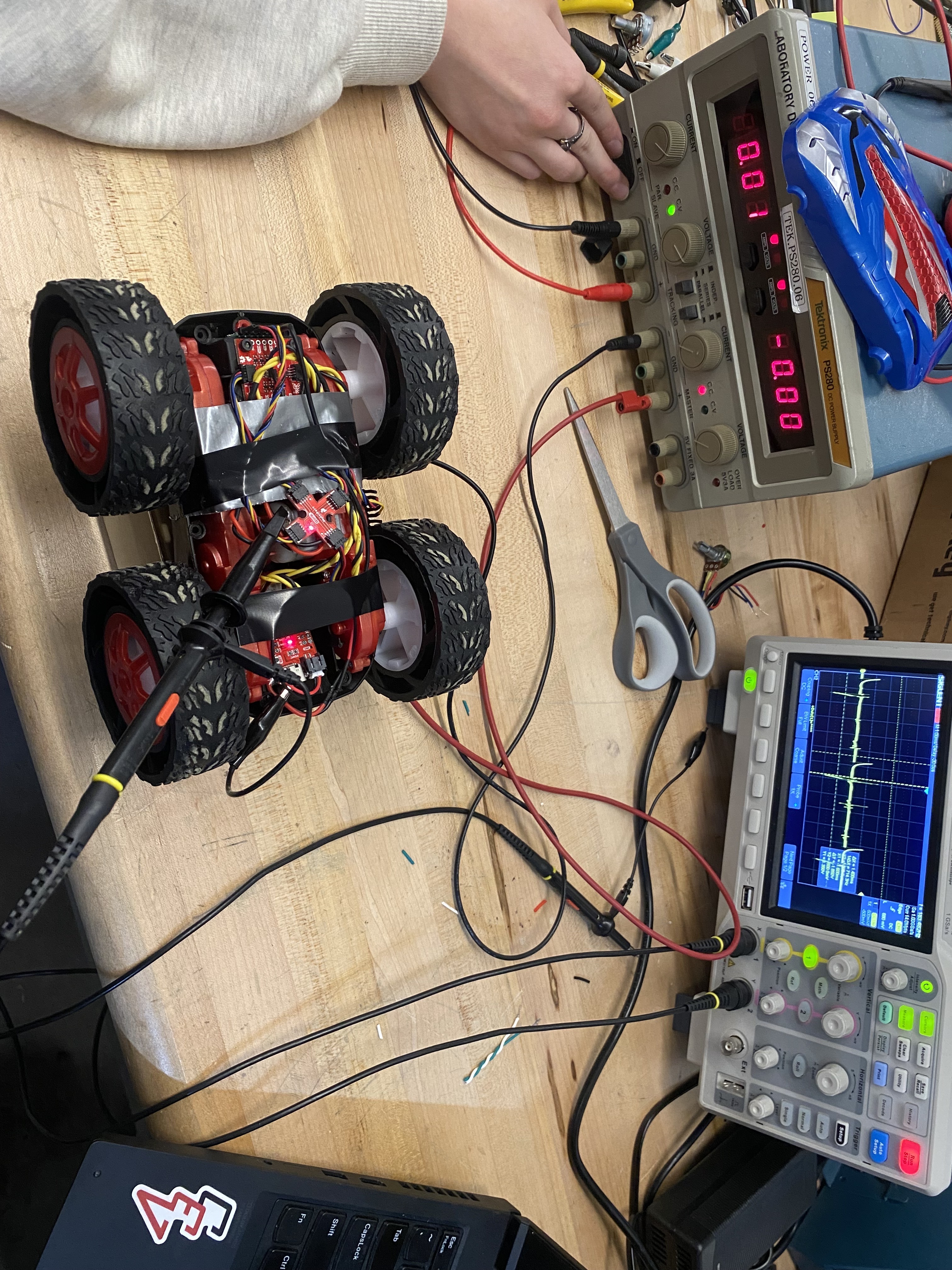
I connected my power supply to the battery input, my 650 mAh battery to the Artemis, and oscilloscope
probe to the motor winding, and set the power supply current compliance to 2 A. Here is what my set
up looked like:
Power Supply Setting
Since the battery voltage was at 3.7 V, that's what I set my power supply voltage to. For current compliance,
I originally set it to 1 A, but I was hitting the limit and the power supply was throttling my voltage, so
increasing the ceiling to 2 A solved this issue.
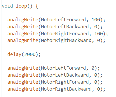
Testing with analogWrite()
As mentioned before, the signals that control the motor are pulse-width modulated, and it's important to check
that the correct signals are being sent. Also, it's important to check that there is not capacitive or inductive
coupling happening with my wires. Here's the code that ran in my test:
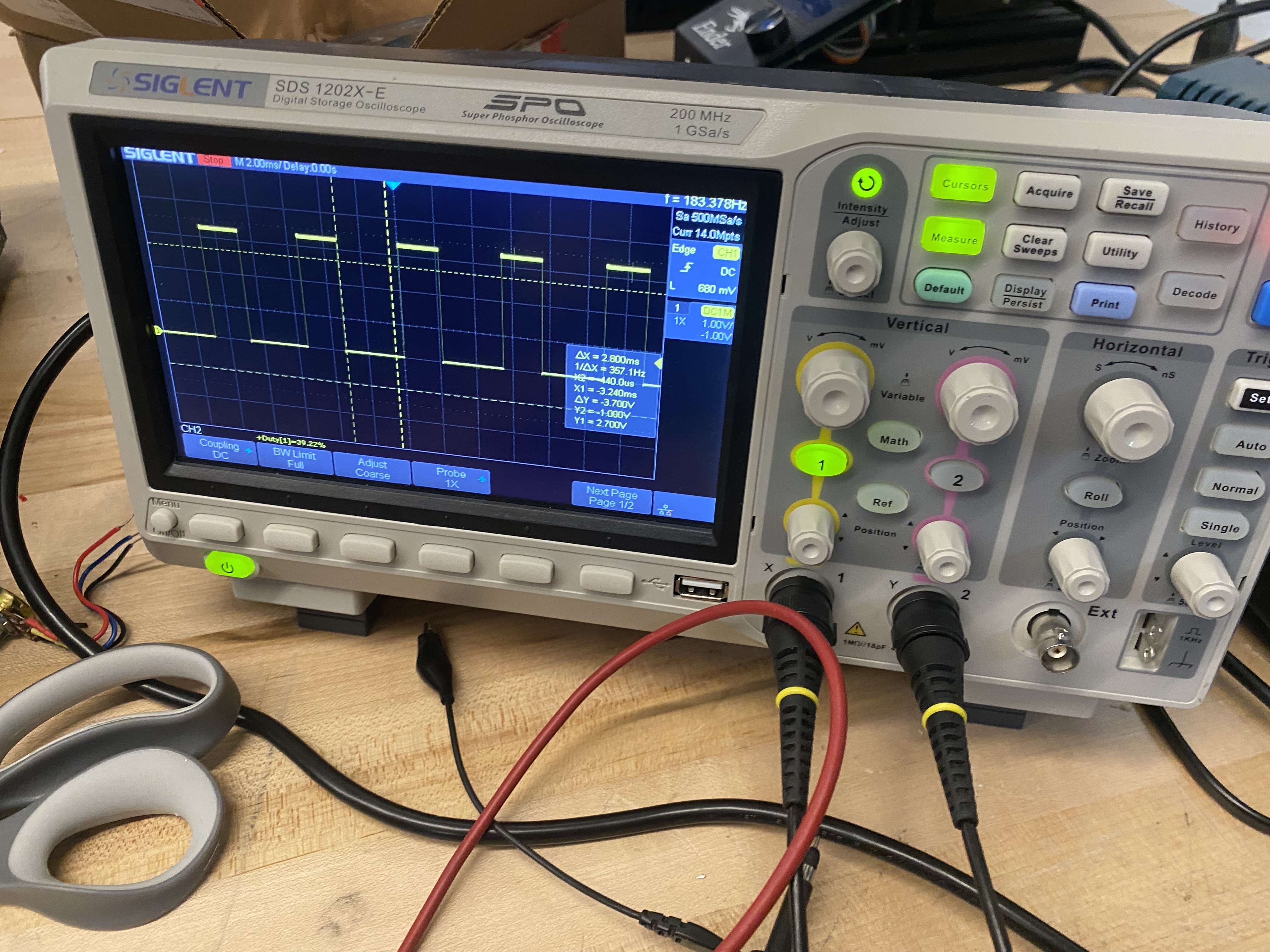
If I probe the pin connected to BOUT1, I should see a PWM signal with a 100/255 (~40%) duty cycle.
That's what I see:
Running the Car
If I power the motor controllers with a battery and hook it up to the motors, it makes the wheels turn:
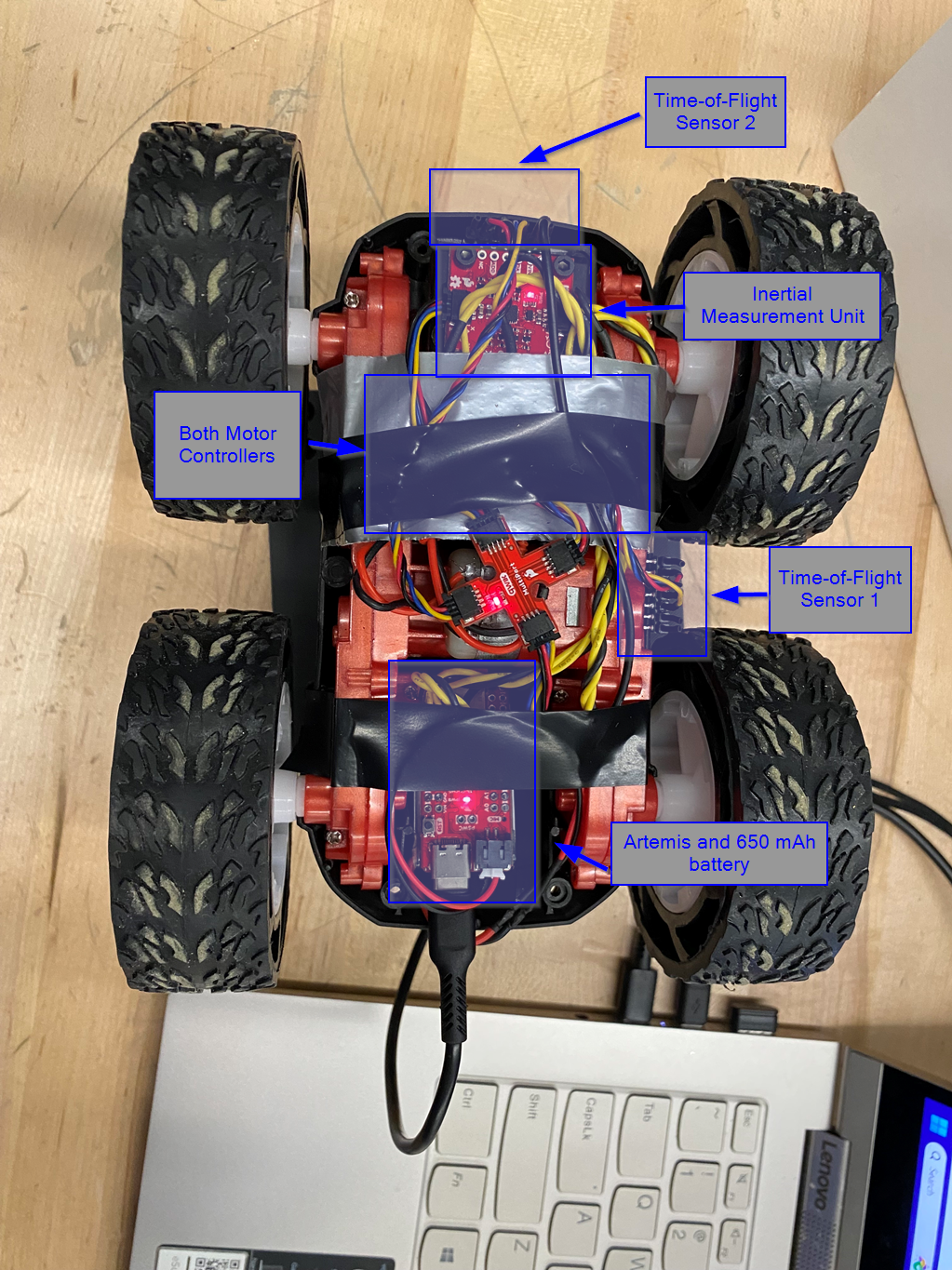
Car Integration
There is a lot to mount on the car, including signal and power components. To minimize EMI and coupling,
I kept loops as small as possible by twisting wires and keeping them short. Also for the sensors, I drilled
holes in the car's frame and screwed them. This allows the ToF and IMU sensors to be fixed to the reference
frame of the car without moving around at all.
Lower PWM Limit
If I send a 1% duty cycle to motors, they won't turn at all due to static friction. So, I need to surpass a
certain threshold in my duty cycle before the car starts moving at its minimum velocity. This changes depending
on battery voltage, but that lower PWM threshold is around 31 and 45 for the right and left motors respectively.
Open Loop Calibration
I had to find the lower PWM limit for each motor earlier due to static friction in each drivetrain. In
addition to static friction, there is also moving friction, and it's different for each side of the car.
So, I also had to add a scaling factor in addition to the offset, and by tuning these scaling factors,
I could make my car drive straight in open-loop control.
I made a function that describes the PWM duty cycle as a function of the throttle with constants for
PWM offset and scaling. The function is:
This makes PWM_duty_cycle a linear function that starts at the point (0, throttle_offset) and
ends at (255, throttle_scaler). If you want full beans, throttle_scaler = 255. Here's the code:
float throttleLeftOffset = 45;
float throttleRightOffset = 31;
float leftScaler = (255.0 - throttleLeftOffset) / 255.0;
float rightScaler = (108.0 - throttleRightOffset) / 255.0;
/*
    * Throttle should be between -255 and 255.
    * Returns 0 if this is true. If throttle is
    * out of range, move() will saturate and return
    * -1
    */
int move(int throttle) {
    int returnValue = 0;

    // If the -255 < throttle < 255,
    // Saturate and return -1.
    if (throttle > 255) {
    throttle = 255;
    returnValue = -1;
    }

    if (throttle < -255) {
    throttle = -255;
    returnValue = -1;
    }

    if (throttle > 0) {
    int throttleLeft = (throttle * leftScaler) + throttleLeftOffset;
    int throttleRight = (throttle * rightScaler) + throttleRightOffset;
    analogWrite(MotorLeftForward, throttleLeft);
    analogWrite(MotorRightForward, throttleRight);
    analogWrite(MotorLeftBackward, 0);
    analogWrite(MotorRightBackward, 0);
    }
    else if (throttle < 0) {
    int throttleLeft = (-throttle * leftScaler) + throttleLeftOffset;
    int throttleRight = (-throttle * rightScaler) + throttleRightOffset;
    analogWrite(MotorLeftBackward, throttleLeft);
    analogWrite(MotorRightBackward, throttleRight);
    analogWrite(MotorLeftForward, 0);
    analogWrite(MotorRightForward, 0);
    } else {
    analogWrite(MotorLeftBackward, 0);
    analogWrite(MotorRightBackward, 0);
    analogWrite(MotorLeftForward, 0);
    analogWrite(MotorRightForward, 0);
    }

    return returnValue;
}
There is also some code to do saturation in case move() gets called with more that it can take.
My right motor is much stronger than my left motor, so I scale my left motor from 255 down to 108.
This is quite drastic, so I'm going to test at higher speeds later and see if I can get away with
less scaling. If I can, then I'll do something more complex than a two-point calibration to map
throttle to PWM duty cycle.
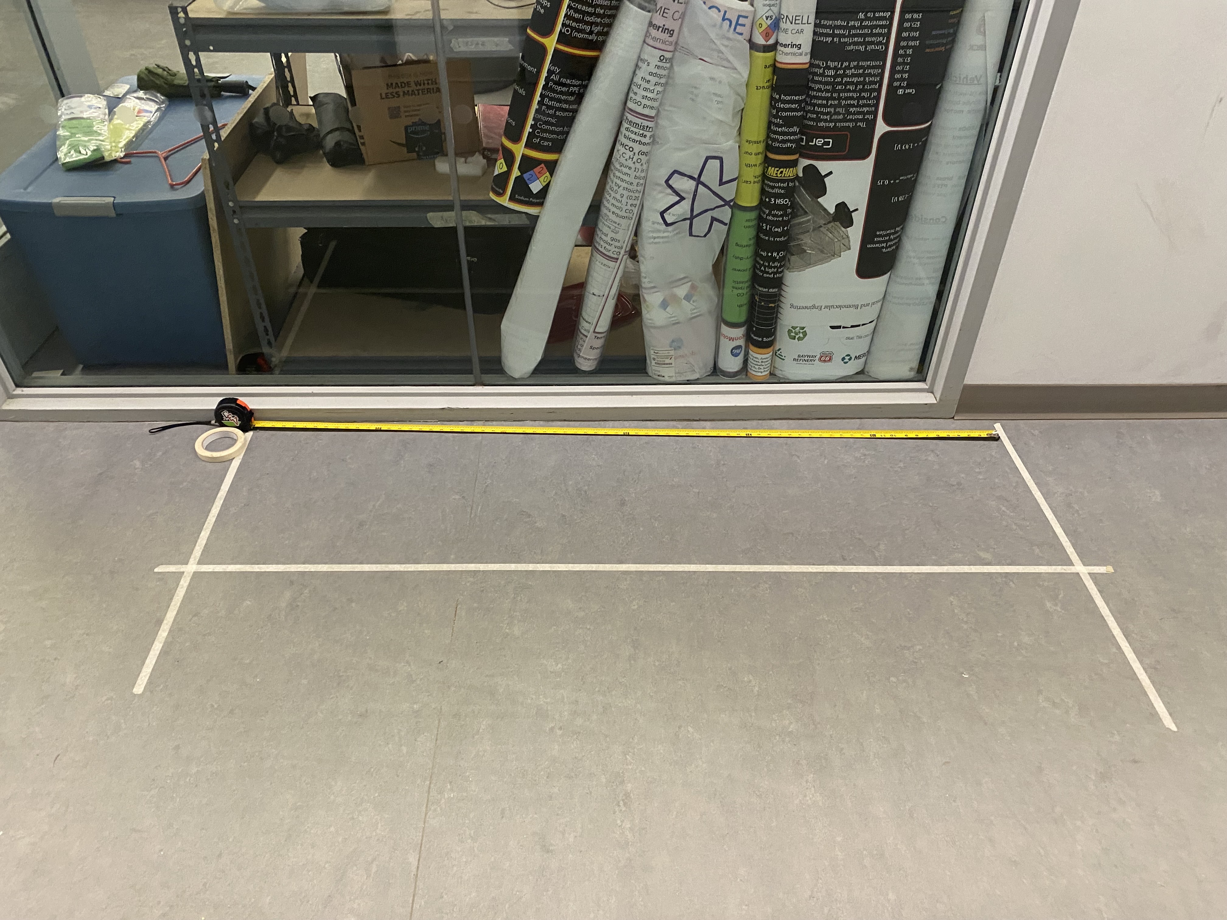
Open Loop Video
I set up a test with a straight strip of tape for 6 feet. Here's what the set up looked like:
Here's a video of my car following the tape for 6 feet. It curves to the left at the end, but this
is just because the motors turn off and the uneven amount of friction in the car causes the car to
turn. While under power, the car drives straight.
I can also make the car turn a little by changing around the PWM values on the left and right.
In the future, I'll add an argument to my move() function so that it includes a turning term.
At this point, I can control my car's wheels to make it drive in a straight line. Separately, I can
also collect data from my IMU and ToF sensors and report that data to my PC. I'm looking forward to
integrating both systems together to make the robot do some cool stuff.